


Temperature, fan, and PSU monitoring: predicting hardware failure
Environmental sensors on network devices are the earliest leading indicators of hardware failure. Temperature trends, fan state changes, and PSU status transitions often precede field-replaceable unit failures by hours or days. The data is not hard to collect, but the MIB landscape is fragmented across vendors, thresholds vary by platform, and inherited polling templates frequently target deprecated OIDs. A template that worked on a Catalyst 3560 can silently return nothing on a Catalyst 8500.
This article covers the MIB stack for environmental monitoring, the specific signals to poll per sensor type, vendor-specific behavior and deprecations, and the correlation patterns that distinguish a localized sensor fault from a device-wide thermal event.
The MIB stack for environmental monitoring
Three MIB layers are in active use across network equipment. Understanding how they join is the prerequisite to building a polling template that works across vendors.
ENTITY-MIB (RFC 4133) provides the physical entity inventory. Each physical component (line card, fan tray, PSU, sensor) has an entry in entPhysicalTable at .1.3.6.1.2.1.47.1.1.1. The entPhysicalDescr field gives a human-readable name. The entity index is the join key used by the other MIBs.
ENTITY-SENSOR-MIB (RFC 3433) is the standards-track MIB for sensor readings. entPhySensorValue at .1.3.6.1.2.1.99.1.1.1.5 returns the numeric reading. entPhySensorStatus at .1.3.6.1.2.1.99.1.1.1.6 returns the operational state. The sensor type (temperature, voltage, fan RPM) is encoded in entPhySensorType at .1.3.6.1.2.1.99.1.1.1.2.
Vendor extensions fill gaps. Cisco uses CISCO-ENTITY-FRU-CONTROL-MIB for power supply and fan operational state on modern platforms. Juniper exposes temperature via jnxOperatingTemp at .1.3.6.1.4.1.2636.3.1.13.1.7 in JUNIPER-MIB.
flowchart TD
    A["ENTITY-MIB entPhysicalTable
.1.3.6.1.2.1.47.1.1.1"] -->|join by entity index| B["ENTITY-SENSOR-MIB
.1.3.6.1.2.1.99.1.1.1"]
    B --> C["entPhySensorValue
numeric reading"]
    B --> D["entPhySensorType
sensor type filter"]
    B --> E["entPhySensorStatus
health state"]
    A -->|join by entity index| F["Vendor FRU MIBs"]
    F --> G["PSU operational state"]
    F --> H["Fan operational state"]
The common pattern: walk ENTITY-MIB to build the entity inventory, then join sensor readings and operational states from ENTITY-SENSOR-MIB using the shared entity index. Vendor FRU MIBs attach to the same entity index for PSU and fan state where ENTITY-SENSOR-MIB does not cover them.
Temperature monitoring
Temperature is the primary leading indicator. A sustained upward trend on an inlet or internal sensor is the earliest sign of cooling degradation, dust accumulation, or impending component failure.
What to poll
Walk entPhySensorValue across the device to get all sensor readings. Use entPhySensorType to filter for temperature sensors (the celsius type per RFC 3433). Cross-reference with entPhysicalDescr to label each sensor by its physical location (inlet, outlet, CPU, switch chip).
# Walk all sensor values (SNMPv3 recommended in production)
snmpwalk -v2c -c <community> <device> .1.3.6.1.2.1.99.1.1.1.5
# Walk entity descriptions for labeling
snmpwalk -v2c -c <community> <device> .1.3.6.1.2.1.47.1.1.1.1.2
# Juniper-specific temperature walk
snmpwalk -v2c -c <community> <device> .1.3.6.1.4.1.2636.3.1.13.1.7
Thresholds
Threshold values vary by platform and sensor. Use vendor-defined thresholds, not arbitrary absolute numbers. RFC 3433 does not define threshold objects; thresholds come from vendor-specific MIBs. Where available, alert above the high-critical value.
These Arista EOS defaults illustrate the range of thresholds you will encounter across a single chassis:
| Sensor type | Typical alert threshold | Typical critical threshold |
|---|---|---|
| Front-panel temp | 65 C | 75 C |
| Fan controller temp | 75 C | 85 C |
| Switch chip temp | 105 C | 115 C |
| VRM temp | 105 C | 110 C |
On Arista EOS, hitting the alert threshold ramps all fans to maximum speed and logs a warning. Hitting the critical threshold shuts down the affected component immediately and the status LED flashes orange.
Inlet vs outlet
Inlet temperature rising across multiple devices in the same rack or row points to a datacenter HVAC issue, not a device fault. Outlet temperature rising on one device while neighbors stay stable points to a device-specific cooling failure (failed fan, dust buildup, degraded thermal interface). Always track sensor location to distinguish these.
Fan monitoring
Fan failure removes cooling capacity and will cause temperature to rise on every downstream sensor in the device. It is the most common precursor to thermal shutdown.
What to poll
Fan state comes from vendor FRU MIBs, not ENTITY-SENSOR-MIB. On Cisco modern platforms, use CISCO-ENTITY-FRU-CONTROL-MIB. The ENTITY-SENSOR-MIB operational status field covers some fan entities but is not universally populated.
Actionability rules:
- Fan state not running is always actionable.
- Fan failed on a redundant fan tray: TICKET (degraded cooling, not an emergency).
- Fan failed on non-redundant cooling: PAGE (thermal failure imminent).
RPM trend
Where fan RPM is exposed (via entPhySensorValue for fan-type sensors), track the trend. A fan whose RPM is steadily declining over days or weeks is failing mechanically even before it reports a fault state. This is one of the few cases where the numeric sensor value matters more than the operational status boolean.
PSU monitoring
PSU state tells you about redundancy and power delivery health. A PSU transitioning from online to a fault state means the device has lost redundancy or is running on a single supply.
What to poll
On Cisco modern platforms, PSU state comes from CISCO-ENTITY-FRU-CONTROL-MIB. Actionability rules:
- PSU state not online (value 2 in cefcFRUPowerOperStatus) is always actionable.
- PSU offline on a non-redundant device: PAGE (power failure imminent).
- PSU offline on a redundant system: TICKET (redundancy lost, not an emergency).
AC loss is not always a failure
On Arista EOS, show system environment all can show a PSU with AC loss (input current = 0) but an OK output status. This is expected behavior for redundant supplies drawing from different power sources. Do not auto-escalate AC loss as a critical event unless the PSU count and redundancy policy warrant it. Check the output status, not just the input state.
Vendor-specific behavior and gotchas
CISCO-ENVMON-MIB is deprecated on modern platforms
The classic CISCO-ENVMON-MIB OIDs under .1.3.6.1.4.1.9.9.13.* are not supported on Catalyst 8500, NCS 5500, and other modern Cisco routing platforms. Cisco moved environmental monitoring to ENTITY-SENSOR-MIB (for numeric readings) and CISCO-ENTITY-FRU-CONTROL-MIB (for PSU and fan operational state).
On classic IOS and IOS-XE platforms (ISR, Catalyst 2960/3560/3750), and on IOS-XR with caveats (ASR 9000), the legacy OIDs still work:
- Temperature:
.1.3.6.1.4.1.9.9.13.1.3.1.3 - PSU status:
.1.3.6.1.4.1.9.9.13.1.5.1.3 - Fan status:
.1.3.6.1.4.1.9.9.13.1.4.1.3
Enable EnvMon traps explicitly with snmp-server enable traps envmon. Traps are not forwarded by default.
False-positive temperature alerts on ASR 9000 and 7600
Persistent false-positive hardware health warnings have been reported on ASR 9001 and 7606 routers when polled via both CISCO-ENVMON-MIB and CISCO-ENTITY-SENSOR-MIB simultaneously. The workaround is to align polling to whichever MIB the device firmware prefers and disable the other poller. Updating the MIB database on your monitoring platform also resolves many false positives.
Catalyst 3560 V1 vs V2 OID divergence
The fan status OID differs between Catalyst 3560 V1 and V2 hardware despite identical model numbers:
- V1:
.1.3.6.1.4.1.9.9.1.222.1.1.3 - V2:
.1.3.6.1.4.1.9.9.13.1.4.1.3
Instrument both OIDs or fingerprint the hardware version before assigning the monitoring template.
Sensor scaling
Sensor values in ENTITY-SENSOR-MIB are scaled integers. Always read entPhySensorScale and entPhySensorPrecision to convert the raw integer to the actual unit. Many monitoring tools handle this automatically. Custom scripts must apply the multiplier explicitly or they will report values that are off by orders of magnitude.
Juniper ambient temperature configuration
Juniper Junos allows configuring the expected ambient temperature:
set chassis ambient-temperature (25C | 40C | 55C)
This setting adjusts the thermal thresholds the device uses internally. Ensure your monitoring thresholds match what the device considers normal for the configured ambient.
Palo Alto Networks
ENTITY-SENSOR-MIB is the recommended MIB for PAN-OS 10.1+. The join to ENTITY-MIB is via entPhysicalDescr mapped to entPhySensorStatus.
Trap-based alerting caveat
Some Broadcom SD-WAN platforms (formerly Viptela) and certain management center platforms stopped passing the human-readable entity name in CISCO-ENTITY-MIB traps. The trap carries only the numeric entity index, which complicates alert triage. Confirm whether your platform passes descriptive strings before relying on trap-based alerting for environmental events.
Correlation patterns
Two correlation axes distinguish useful alerts from noise.
One bad sensor vs device-wide issue. When a single temperature sensor spikes but others on the same device remain stable, the problem is likely that sensor’s local cooling (a nearby fan failed, a heatsink degraded). When multiple sensors across the same device rise together, the device is experiencing a systemic thermal event (HVAC failure, multiple fan failures, or ambient temperature exceeding design limits).
Sensor state vs syslog/trap confirmation. Environmental polling should be correlated with hardware-failure syslog messages and SNMP traps. A temperature reading above threshold that is also accompanied by a syslog hardware alarm is a confirmed event. A temperature reading above threshold with no corroborating syslog may be a sensor calibration issue or a polling artifact (see the ASR 9000 false-positive pattern above).
# Check device-side environment state (read-only, safe)
ssh <device> 'show environment all'
# Verify Juniper ambient configuration
ssh <device> 'show chassis environment'
Signals to watch in production
| Signal | Why it matters | Warning sign |
|---|---|---|
| Temperature value per sensor | Leading indicator of thermal failure | Sustained upward trend, or any reading above vendor critical threshold |
| Temperature operational status | Binary sensor health state | Transition from ok to non-ok state |
| Inlet temperature across rack or row | Datacenter HVAC health | Multiple devices showing simultaneous inlet rise |
| Outlet temperature per device | Device-specific cooling health | One device rising while neighbors stay stable |
| Fan operational state | Cooling capacity | Fan state not running |
| Fan RPM trend | Mechanical wear prediction | RPM declining over days or weeks before fault state |
| PSU operational state | Power redundancy | PSU state not online |
| PSU input status | Input power health | AC loss with OK output is expected on redundant supplies |
| SNMP trap: environmental threshold exceeded | Push notification of threshold crossing | Reception depends on explicit trap enablement |
| Syslog: hardware alarm messages | Device-asserted event | Correlate with sensor polling for confirmation |
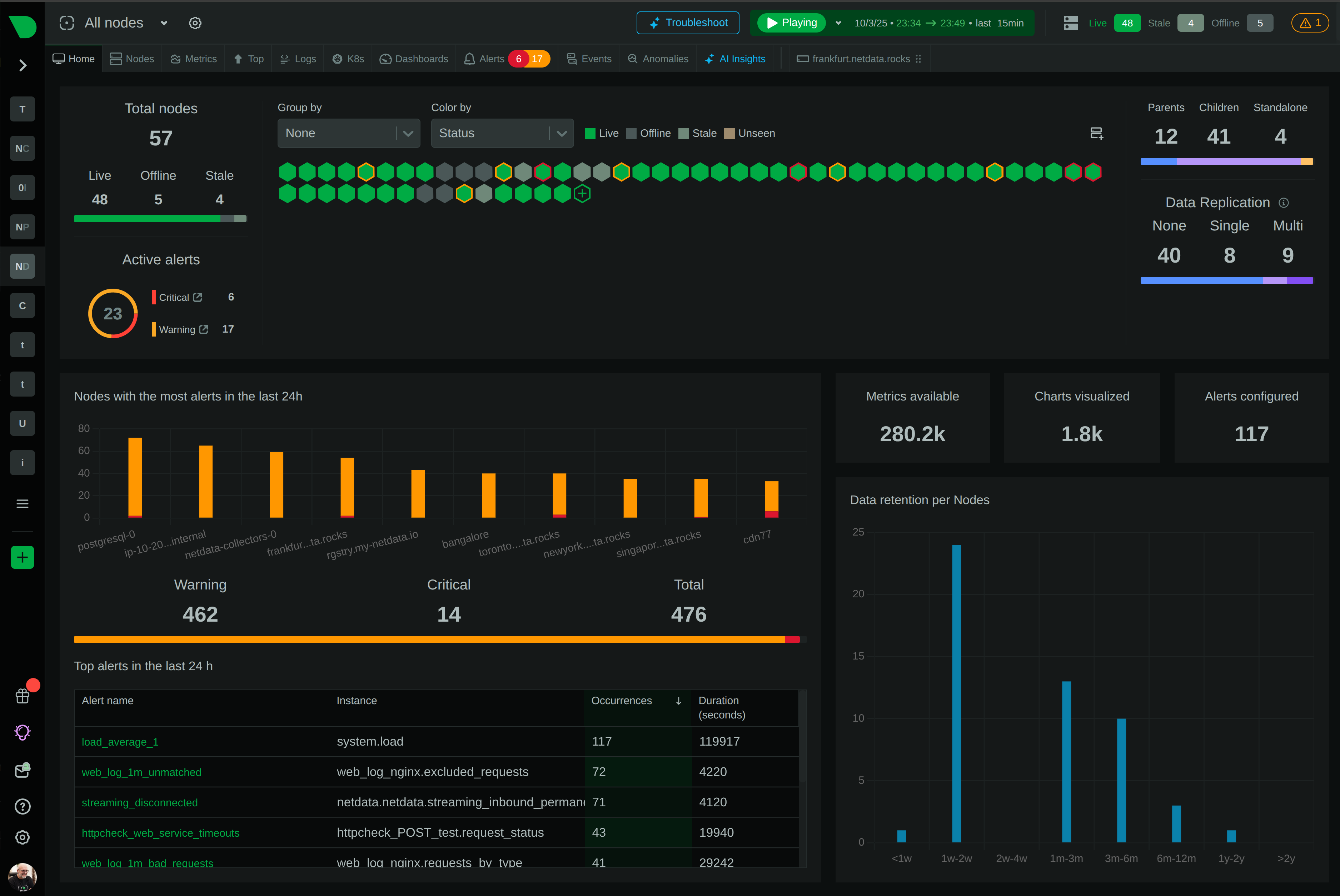
How Netdata helps
- Netdata’s SNMP collector polls ENTITY-SENSOR-MIB
entPhySensorValueandentPhySensorStatusacross all physical entities, joining temperature readings with entity descriptions from ENTITY-MIB for labeled, per-sensor charts. - Temperature trends are stored at per-second resolution, making gradual drift visible long before a threshold is crossed. Fan RPM decline over days or weeks is detectable in the trend view without manual threshold tuning.
- When a PSU transitions to a fault state, Netdata correlates the environmental signal with device-level syslog and SNMP trap events in the same timeline, so you can see whether the PSU failure was preceded by a power event, a temperature spike, or a fan failure.
- Per-sensor anomaly detection flags deviations from the learned baseline for each specific sensor, accounting for the fact that normal operating temperature differs between a switch chip and a fan controller.
- Alert templates can differentiate between redundant and non-redundant configurations: PSU failure on a single-supply device triggers a PAGE, while the same failure on a dual-supply device triggers a TICKET.
Related guides
- ARP cache staleness: when IP-to-MAC mapping goes bad
- Asymmetric routing: why your path and latency measurements lie
- Audit log gaps: detecting syslog/trap tampering or loss
- BGP flapping: why a peer keeps resetting and how to find the cause
- BGP NOTIFICATION and Cease messages: what each subcode is telling you
- BGP RIB and FIB growth: monitoring route-table size before it bites
- BGP route leak and hijack: the detection signals and alerts that matter
- BGP session Established but stale: detecting silent route loss
- Correlating cloud VPC flow logs with on-prem NetFlow
- Cold-start topology: why your map is incomplete after a collector restart
- NIC RSS misconfiguration: one CPU core silently dropping your telemetry
- Locating endpoints behind NAT and wireless: the positioning problem