


STP topology-change storms: reconvergence cascades explained
A topology-change notification (TCN) is not itself a failure. STP generates one every time a non-edge port transitions up or down. That is normal during maintenance, link recovery, or device boot. The problem is what happens next. When TCNs fire repeatedly, or when a single TCN hits a large Layer 2 domain with thousands of MAC addresses, the protocol’s designed response becomes a self-inflicted traffic event.
The cascade is mechanical. Every switch that receives the topology-change flag shortens its MAC address aging timer from the default (typically 300 seconds) to the Forward Delay value (15 seconds by default). This forces unknown-unicast flooding until endpoints re-announce their MACs through normal traffic. In a VLAN with thousands of entries, that flooding saturates links, spikes latency, and consumes switch CPU. The blast radius is the entire broadcast domain, not the switch where the port flapped.
TCN propagation and MAC flush mechanism
A bridge that detects a port state transition on a non-edge port generates a TCN BPDU and sends it upstream toward the root bridge via its root port. The root bridge does not originate TCNs. It acknowledges the notification and then sets the Topology Change (TC) flag in its outgoing Configuration BPDUs for a propagation window of Max Age plus Forward Delay. With STP defaults, that is 20 + 15 = 35 seconds.
During that window, every switch that receives a Configuration BPDU with the TC flag set cuts its MAC aging timer to the Forward Delay value. The design intent is logical: entries that pointed to the old topology should expire quickly so traffic can relearn the new path. The side effect is less benign. MAC tables flush en masse, and any destination MAC not yet relearned is flooded out all forwarding ports in the VLAN simultaneously.
This matters operationally for two reasons. First, the blast radius is the entire VLAN, not the local switch. A flapping access port on a switch in one building flushes MAC tables on switches in other buildings, flooding unrelated traffic across inter-switch trunk links. Second, if the trigger is a continuously flapping port, the TCN fires on every transition and the domain never stabilizes. Each cycle produces another wave of flooding, and switch CPUs tasked with MAC table management and BPDU processing are consumed by convergence work rather than forwarding traffic.
How the cascade unfolds
flowchart TD
    A["Access port flaps
on non-edge port"] --> B["Local switch generates
TCN BPDU"]
    B --> C["TCN travels upstream
via root port"]
    C --> D["Root bridge
receives TCN"]
    D --> E["Root sets TC flag in
Config BPDUs for
Max Age + Forward Delay"]
    E --> F["All switches receive
TC-flagged BPDU"]
    F --> G["MAC aging cut from
300s to 15s"]
    G --> H["MAC table flush +
unknown-unicast flood"]
    H --> I["Traffic relearned
via normal frames"]
A non-root switch generates a TCN BPDU when a port transitions up or down and that port is not configured as an edge port (PortFast on Cisco, edge port on Juniper). The TCN travels upstream through the root port of each switch until it reaches the root bridge. The root acknowledges the TCN and sets the TC flag in the Configuration BPDUs it sends downstream.
That TC flag propagates through the entire tree for Max Age plus Forward Delay (35 seconds with legacy defaults). Every switch that sees the TC flag cuts its MAC aging timer to the Forward Delay value. Entries age out in seconds rather than minutes, and any MAC not relearned by then is flooded.
Convergence time depends on which STP version is running.
Legacy STP (IEEE 802.1D) uses timer-driven port state transitions. A port moving to forwarding passes through Blocking, Listening (Forward Delay seconds), and Learning (Forward Delay seconds) before reaching Forwarding. The full convergence path, including Max Age expiry on the old path, can take up to 50 seconds (Max Age 20 + Forward Delay 15 + Forward Delay 15). Even without Max Age expiry, Listening plus Learning alone consume 30 seconds.
RSTP (IEEE 802.1w) replaces the timer-driven sequence with a proposal-agreement handshake on point-to-point links. Convergence for a direct link failure happens within 3 times the Hello Time, typically 6 seconds at the default Hello interval of 2 seconds. RSTP also replaces the root-bridge TC propagation window with a per-port TC While timer. The MAC flush still happens, but the window is shorter and the forwarding topology stabilizes faster.
The critical point: regardless of STP version, the MAC table flush is not optional. It is the protocol’s mechanism for purging stale topology entries. The difference between legacy STP and RSTP is how long the flush window lasts and how quickly forwarding stabilizes. In both cases, a continuously flapping port produces continuous TCNs and continuous flushing.
Where it shows up in production
- Port flapping without edge-port configured. Any non-edge port that flaps triggers a TCN on every transition. The canonical case: an end-station NIC that flaps repeatedly, a bad cable or SFP on an access port, or a device with a failing power supply. Without PortFast or edge-port on the access port, each flap is a full TCN event with domain-wide consequences.
- Mixed STP versions across the domain. Running legacy STP on some switches and RSTP or MSTP on others forces the faster variants into compatibility mode. Each flap reverts to the 30 to 50 second timer-based convergence of legacy STP, and rapid convergence benefits are lost for the duration of the mixed domain.
- ISC or MLAG peering links with STP enabled. Enabling STP on inter-switch connectivity (ISC) or MLAG peering links can cause unexpected topology interactions and TCN flooding between the peering devices. Check your vendor’s MLAG documentation before changing STP on peer links.
- Underpowered switches in the path. High-frequency TCN BPDUs consume switch CPU for MAC table management. On underpowered or unmanaged switches, STP processing delays compound the instability, extending the disruption beyond what the timers alone would produce.
- Rogue root bridge from misconfiguration or injection. A bridge that wins root election unexpectedly, whether from a priority misconfiguration or an injected device with priority 0, forces the entire topology to reconverge. The new topology may route traffic through paths and links not designed to carry it.
Configuration traps and common misuses
- Edge port silently ignored under legacy STP. If you configured edge ports but the spanning-tree instance is running original IEEE 802.1D STP, the edge-port setting may be silently ignored. Every end-station connect and disconnect still generates a TCN. On Cisco, PortFast works under PVST+ and suppresses TCNs; on standards-compliant 802.1D without vendor extensions, the edge-port concept does not exist.
- BPDU Filter disabling STP protection. Applying bpdufilter to an interface silently drops BPDUs in both directions and effectively disables STP on that port. If two BPDU-filtered ports are cross-connected, a Layer 2 loop forms with no STP protection. The filter is not a tuning option. It is an STP bypass.
- BPDU Guard without errdisable recovery. When BPDU Guard shuts a port into errdisable state, manual intervention (shutdown and no shutdown) or explicit errdisable recovery configuration is required. The default recovery interval, if configured, is 300 seconds. Without recovery configured, the port stays disabled until an operator intervenes.
- Root Guard and Loop Guard on the same interface. An interface can be configured for either Root Guard or Loop Guard, not both. Root Guard blocks superior BPDUs from a downstream switch that should not become root. Loop Guard blocks ports that stop receiving BPDUs, which indicates a unidirectional link failure. Configuring both on the same interface is a configuration error, not a defense-in-depth strategy.
- PVST+ and MST interoperability blindness. Cisco PVST+ sends per-VLAN BPDUs to a Cisco-specific multicast address for tagged VLANs. Pure IEEE 802.1Q bridges, including Dell, Arista, and Juniper, only see the Common Spanning Tree (CST) unless they also listen on that address. Misalignment between Cisco PVST+ and non-Cisco MST causes topology blindness on the non-Cisco segments, where STP state is invisible for affected VLANs.
Signals to watch in production
| Signal | Why it matters | Warning sign |
|---|---|---|
STP topology change count (dot1dStpTopChanges at .1.3.6.1.2.1.17.2.4) | Cumulative counter of TCN events, tracked as a rate over time | Rate > 5/min sustained, or burst after stable baseline |
Root bridge identity (dot1dStpDesignatedRoot at .1.3.6.1.2.1.17.2.5) | Unexpected root means topology reconverged around a non-designated path | Root changed without change ticket |
| linkDown / linkUp trap pairs | Identifies the originating port of each TCN | Pair frequency > 1/sec on any interface |
| ifOperStatus transitions | Confirms physical state changes behind the TCN burst | Flapping > 3 transitions/min on one interface |
| Device control-plane CPU | TCN processing and MAC table management consume CPU | Spike to 90%+ during convergence on switches in the VLAN |
| Latency probes on L2 paths | Reveals the user-impact window of flooding and relearning | RTT spike or packet loss during convergence that resolves after MAC tables stabilize |
| FDB / MAC table size | Mass flush shows as sudden count drop followed by relearn | Sudden drop > 50% in < 5 min |
| Broadcast and unknown-unicast rate | Flooding is the direct traffic multiplier from MAC table flush | Rate spike correlated with TCN count increase |
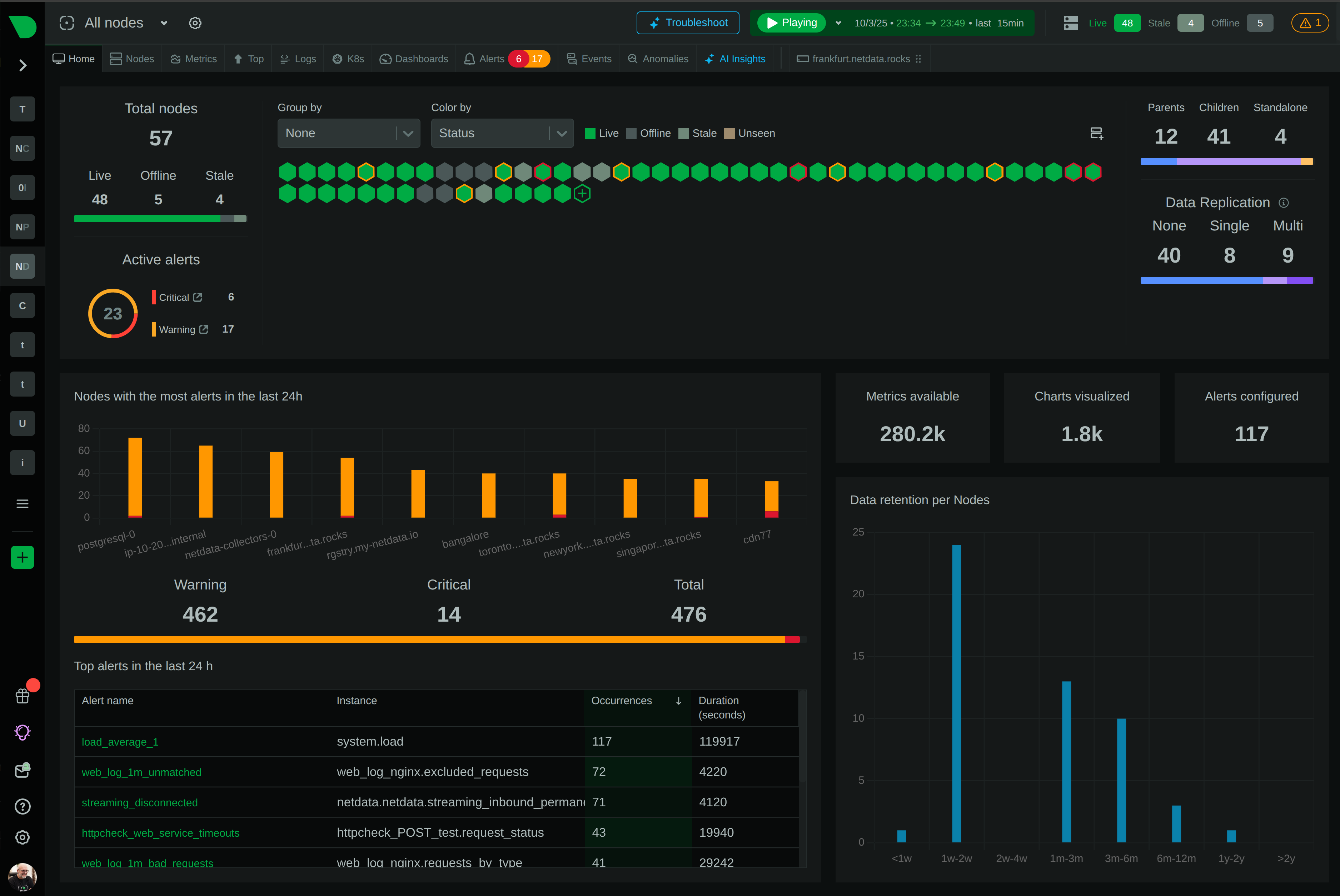
How Netdata helps
- Netdata collects
dot1dStpTopChangesanddot1dStpDesignatedRootvia SNMP from BRIDGE-MIB, letting you visualize topology change rate and root bridge identity over time and alert on unexpected changes without writing custom pollers. - Correlate STP topology changes with linkDown/linkUp traps and ifOperStatus transitions in a single timeline. The originating port of a TCN cascade is the one whose state transitions immediately precede the topology change count spike.
- Track device control-plane CPU alongside topology change count to distinguish a routine convergence event (brief CPU bump, TCN count returns to zero) from a sustained TCN storm (CPU stays elevated, TCN count keeps climbing).
- Overlay latency probe data on STP events to quantify how long the MAC table flush disrupted user traffic.
- Monitor FDB and MAC table size to see the flush-and-relearn cycle directly. A sudden drop followed by gradual recovery confirms the cascade and tells you when the domain has stabilized.
Related guides
- Asymmetric routing: why your path and latency measurements lie
- BGP flapping: why a peer keeps resetting and how to find the cause
- BGP NOTIFICATION and Cease messages: what each subcode is telling you
- BGP RIB and FIB growth: monitoring route-table size before it bites
- BGP route leak and hijack: the detection signals and alerts that matter
- BGP session Established but stale: detecting silent route loss
- NetFlow storage sizing: how much disk your flow collector really needs
- Flow export-to-ingest latency: why your NetFlow data is minutes behind
- Network monitoring checklist: the signals every production network needs
- NetFlow v9/IPFIX template desync: flows decoded wrong or dropped after a reboot
- Silent UDP flow data loss: why your NetFlow collector is dropping records
- NetFlow vs sFlow vs IPFIX: what they measure and how each one fails