












Most NVMe thermal monitoring is live-state monitoring: you watch composite temperature and alert when it crosses a threshold. That works while you are looking. It tells you nothing about the 40 minutes last night when a backup job pushed an M.2 drive past its warning threshold and the controller quietly throttled your database.
Two fields in the NVMe SMART/Health Information log close that gap: warning_temp_time (Warning Composite Temperature Time) and critical_comp_time (Critical Composite Temperature Time). They are cumulative counters, in minutes, recording how long the drive has spent above its Warning Composite Temperature Threshold (WCTEMP) and Critical Composite Temperature Threshold (CCTEMP). They are the drive’s own thermal-stress history, kept whether or not anyone was watching.
Because they are cumulative and never decrease, the absolute value is mostly trivia. The rate of change is the signal. This article covers what the counters actually count, how to read them, and the three ways they lie to you.
What these counters are
Both fields live in the SMART/Health Information log (Log Identifier 02h) and are reported by nvme smart-log as “Warning Temperature Time” and “Critical Composite Temperature Time”. smartctl -a exposes the same fields as “Warning Comp. Temperature Time” and “Critical Comp. Temperature Time”.
warning_temp_time: cumulative minutes the controller has been operational with composite temperature at or above WCTEMP (and below CCTEMP).critical_comp_time: cumulative minutes with composite temperature at or above CCTEMP.
Two properties of the underlying thresholds matter before you interpret anything:
- WCTEMP and CCTEMP are vendor-set per model. They live in Identify Controller data, not in the SMART log, which is why most monitoring tools never show them. Typical consumer drives use WCTEMP around 70-80°C and CCTEMP around 85°C; enterprise drives often run higher.
- Composite temperature is not a physical sensor reading. It is an implementation-specific computed value that may not correspond to any single physical point in the NVM subsystem. Per-sensor temperatures (visible via hwmon) can diverge from it.
Netdata collects both counters and exposes them as the contexts nvme.device_warning_composite_temperature_time (dimension wctemp) and nvme.device_critical_composite_temperature_time (dimension cctemp), converting the raw minutes to seconds.
How the counters work
The controller samples its composite temperature against the two thresholds while operational. For each minute the temperature sits at or above WCTEMP, warning_temp_time increments. For each minute at or above CCTEMP, critical_comp_time increments. Neither counter ever decrements, resets on reboot, or clears after the drive cools down.
flowchart TD
  S[Composite temperature sampled while controller operational] --> W{At or above WCTEMP?}
  W -->|no| N[No counter increments]
  W -->|yes| C{At or above CCTEMP?}
  C -->|no| WT[warning_temp_time +1 minute]
  C -->|yes| CT[critical_comp_time +1 minute]
  WT --> TH[Controller throttling to self-protect]
  CT --> CR[Thermal emergency zone, shutdown risk]
One dependency silently disables the whole mechanism: if WCTEMP or CCTEMP is reported as 0h in Identify Controller data, the corresponding counter is always 0 regardless of actual temperature. The NVMe spec revision 1.2 and later requires compliant controllers to report a non-zero WCTEMP (and CCTEMP); older controllers may report 0h, which forces the counters to read zero forever.
The counters are 32-bit fields and effectively saturate. The spec spells out a no-wrap rule (“shall not wrap once FFFFFFFFh is reached”) only for the thermal management counters; it does not state one for these two, but you will not see them roll over to zero in practice.
A unit note that trips people up: these two counters are in minutes, but the Thermal Management T1/T2 Total Time fields in the same log page are in seconds. Comparing warning_temp_time against thm_temp1_total_time without converting makes one of them look 60 times larger than reality.
Reading the counters manually
# Pull the two thermal-stress counters from the SMART log
nvme smart-log /dev/nvme0 | grep -i "warning_temp_time\|critical_comp_time"

# Get the thresholds they count against (Identify Controller data, not SMART)
nvme id-ctrl /dev/nvme0 | grep -i "^wctemp\|^cctemp"

# Context: how long has the drive been alive?
nvme smart-log /dev/nvme0 | grep "power_on_hours"
nvme id-ctrl reports WCTEMP and CCTEMP in Kelvin; subtract 273.15 for Celsius. If either prints as 0, the matching counter is disabled and will always read zero.
The useful arithmetic:
- Time in thermal stress as a fraction of drive life.
warning_temp_time / (power_on_hours * 60)tells you what percentage of the drive’s powered-on life it has spent throttling. Low single digits on a busy database server is plausible; 10% or more means the drive is routinely thermally constrained and your effective sustained throughput is lower than you think. - Rate of change between samples. Read the counter now, read it again in an hour. Any increment means the drive crossed the threshold during that window, even if current temperature looks fine. This is how you catch thermal events that happened between polling intervals or overnight.
- Warning vs critical ratio. A drive with large
warning_temp_timebut zerocritical_comp_timeis throttling as designed and self-protecting. Any non-zerocritical_comp_timemeans the drive entered the zone where the vendor considers continued operation dangerous.
The three ways these counters lie
A persistent zero does not mean the drive never got hot. This is the most common misreading. Many drives never implement warning_temp_time at all: the counter reads 0 for the drive’s entire life even on heavily abused hardware. Other drives report WCTEMP as 0h, which disables the counter by spec. Before trusting a zero, confirm the drive reports a non-zero WCTEMP via nvme id-ctrl. If it does not, you have no thermal-history counter and must rely on live temperature monitoring alone.
A static non-zero value is history, not a current problem. The counters never decrease. A value of 4,200 minutes might reflect a summer cooling failure two years ago that was fixed the same week. A non-zero value with a zero rate of change tells you the drive was thermally stressed at some point in its life, which is relevant context for interpreting wear (high temperature history accelerates NAND degradation and appears in the “Silent Data Degradation” failure pattern), but it is not an active incident.
The counters and critical_warning bit 1 can disagree. Critical warning bit 1 (temperature threshold exceeded) is a live-ish flag set by firmware; the time counters are the accumulated record. There are field reports (e.g. on consumer drives after firmware updates) of firmware bugs that assert bit 1 on cool drives while the time counters correctly stay at zero; the specific models vary with firmware. If bit 1 is set but current composite temperature is well below WCTEMP and neither counter is incrementing, suspect firmware before you suspect cooling, and check for a firmware update.
What the values tell you operationally
| Observation | Meaning | Response |
|---|---|---|
warning_temp_time incrementing during known heavy load | Drive crosses WCTEMP under workload and throttles to cope | TICKET. Fix cooling or spread load; throttling is silently taxing latency |
warning_temp_time incrementing with no explanation | Thermal events you are not seeing live: overnight jobs, seasonal ambient rise | TICKET. Correlate the increment window with workload and ambient temperature |
critical_comp_time incrementing | Drive entered the critical thermal zone | Urgent investigation. Verify cooling, fans, heatsink contact immediately |
Critical warning bit 1 sustained > 5 minutes AND critical_comp_time increasing | Active, non-self-resolving thermal emergency | PAGE. Reduce load now; the drive is near autonomous shutdown |
| Both counters zero, WCTEMP reported as 0h | Counters not implemented, zero is meaningless | Rely on live composite temperature monitoring instead |
| Non-zero but flat for months | Resolved historical event | Context only. Note it when interpreting wear and media errors |
High temperature history also changes how you read endurance data. NAND retention and endurance degrade faster at elevated temperature, so a drive with large accumulated thermal-stress minutes deserves more scrutiny of media_errors and available_spare than its percentage_used alone would suggest.
Signals to watch in production
| Signal | Why it matters | Warning sign |
|---|---|---|
warning_temp_time rate of change | The actionable form of the counter: is the drive entering thermal stress now | Any sustained increase |
critical_comp_time rate of change | Minutes spent above CCTEMP, the danger zone | Any non-zero increase |
Composite temperature (nvme.device_composite_temperature) | Live state the counters integrate over | Approaching WCTEMP under normal load |
Critical warning bit 1 (temp_threshold dimension) | The drive’s own threshold-crossing assertion | Sustained assertion plus rising critical_comp_time |
Thermal management transitions (thm_temp1_trans_count, thm_temp2_trans_count) | How often the controller actually throttled; TMT total time (in seconds) quantifies the performance cost | Rising transition counts |
| Throughput and latency during counter increments | Confirms throttling is the cause of a slowdown, not GC or media issues | Throughput drop correlated with temperature rise |
power_on_hours | Denominator for computing what fraction of drive life was spent hot | Needed for any meaningful ratio |
The thermal death spiral pattern chains these together: temperature rises, warning_temp_time starts accumulating, throughput declines, latency climbs, TMT transitions increment, and finally bit 1 asserts. Catching the pattern at the second step, from the counter rate, is much cheaper than catching it at the last one.
How Netdata helps
- Netdata charts both counters as
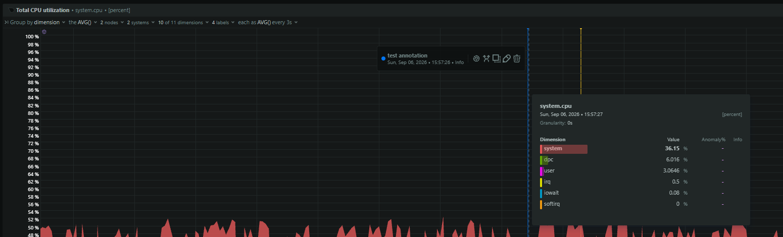
nvme.device_warning_composite_temperature_timeandnvme.device_critical_composite_temperature_time, converting the raw minute counters to seconds, so increments are visible on the dashboard instead of requiring manualnvme smart-logdiffs. - Because the charts are continuous, you can see exactly when an increment happened and overlay it against the workload window, which is the information you need to attribute a thermal event to a backup job, a compaction, or an ambient cooling failure.
- The composite temperature chart (
nvme.device_composite_temperature) on the same dashboard gives the live state; counter rate plus live temperature together distinguish “throttling right now” from “was hot earlier”. - Critical warning bit 1 is broken out as the
temp_thresholddimension ofnvme.device_critical_warnings_state, so you can alert on the escalation path the playbook defines: sustained bit 1 plus risingcritical_comp_time. - Thermal management transition charts (
nvme.device_thermal_mgmt_temp1_transitions_rate,nvme.device_thermal_mgmt_temp2_transitions_rateand the corresponding total-time charts) quantify how often the drive throttled and for how long, closing the loop between thermal stress and observed performance.
Related guides
- NVMe available spare below threshold: critical warning bit 0 and end-of-life wear
- NVMe available spare declining: watching the wear trajectory before the threshold
- blk_update_request: I/O error, dev nvme0n1: reading NVMe I/O errors in the kernel log
- NVMe controller reset loop: repeated resets from a firmware hang
- nvme nvme0: I/O timeout, Resetting controller: what an NVMe controller reset means
- NVMe controller state not live: reading resetting, deleting, and dead from sysfs
- NVMe critical_warning is nonzero: decoding the SMART critical warning bitmask
- NVMe device disappeared: nvme0: Removing and a drive that fell off the PCIe bus
- NVMe endurance runway: projecting time-to-replacement from wear signals
- How NVMe actually works in production: a mental model for operators
- NVMe media_errors increasing: uncorrectable data-integrity errors on NAND
- NVMe monitoring checklist: the signals every production SSD needs